
This was my final year project in my undergrad. Internet of Things was always a dream project for me. The major goals of my project were to:
- Control my home appliances.
- Monitor room temperature, humidity levels.
- Get Notified by fire alerts, burglary alerts.
This project involved both hardware and UI designing. The hardware components used in the prototype of the project were Arduino microcontroller, Wiznet Arduino Ethernet Shield, DHT-11 temperature and humidity sensor, LEDs, Resistors, relays, etc.
The software part included several programming languages and platforms like Arduino IDE, HTML, CSS, PHP, XOBXOB Cloud Services, JavaScript, jQuery, Bootstrap, RESTful API and so on.
There were three basic operating sub-systems in the system. They are:
- Webpage UI which is a user interface designed to display the sensors values as well as control buttons to the electrical appliances.
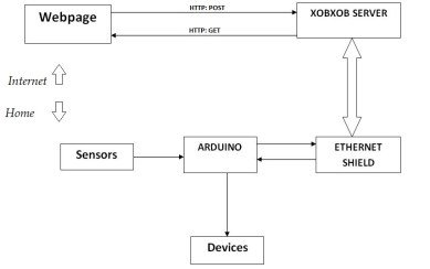
- XOBXOB platform which acts as a bridge between the user and the home controller. It connects the server side Arduino to the client side webpage as well handle all the database and manages the data transfer protocols.
- Arduino microcontroller which collects the sensors values from the room, sends it to XOBXOB server via Ethernet shield using its API and gets control values for devices from the XOBXOB server to send information to relays to turn on/off the appliances.
XOBXOB is a simple cloud service that makes it easy for projects to connect to the Internet of Things. It creates small mailboxes (XOBs). Things can send and receive messages through a XOB. By sharing XOBs, things can send messages to each other. More detailed info about XOBXOB can be found at it’s official site: www.xobxob.com
The following picture shows the very basic block diagram of my project:
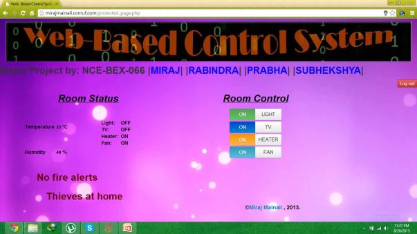
The first sub-system of my project is the User Interface. I have made a small webpage that is continuously synced with the XOBXOB server to exchange various data values. Also, the user interface provided by the XOBXOB itself can be used. It is more handy in smartphones. For seurity purposes, both the user interface platforms are well secured by user password so that only the authorized personnel can use this system. Various languages and scripts has been used to design the webpage. The current location of the demo webpage used for prototype can be found here.
The snapshots of both of the user interfaces is attached below:
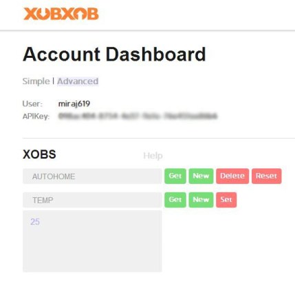
The second sub-system is the XOBXOB platform where I have created an account. I created a XOB named AUTOHOME and many parameters like LIGHT, HEATER, TEMP, HUMID and so on under it. The XOBXOB provides an API key which is used by controller to track down XOBXOB server and connects to it.
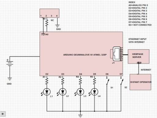
The third and most important sub-system is the Arduino part where an Arduino ethernet shield connected to CAT 6 LAN wire is placed above Arduino microcontroller. The temperature, humidity, fire alarm and burglary sensors as well as relays for switching several devices are connected to the controller. This is the part that actually resides at the room. The controller needs constant 5V DC power supply and internet connection.
Two microcontroller program is divided into two modules. The first one is used to receive the device switch controls from the webpage via XOBXOB server and another module is used to update the sensor values to the webpage via XOBXOB server. These two programs are kept in a loop with a delay of 30 seconds so that new values are updated and result is reflected every 30 seconds later.
The schematic connection of the hardware is as follow:
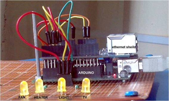
Similarly, the following two pictures are the snapshots of the first working prototype of the project:
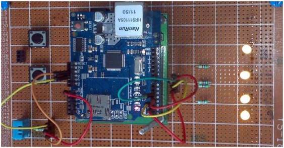
So, after the successful completion of the prototype testing of this project, I am on my way to develop this project as a commercial product.
All the related documents regarding this project can be provided upon special request. Also, the detailed report of this project can be found at the library of National College of Engineering, Kathmandu, Nepal.
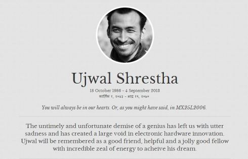
My heartful condolence on the untimely demise of my Electronics trainer, Ujwal Shrestha who had helped me a lot in this project.
 MIRAJ MAINALI